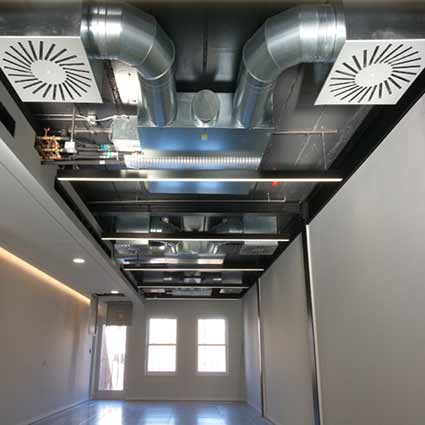
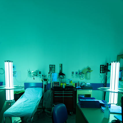
Improve your UV and lighting systems with highly reflective media
Our highly Lambertian portfolio of reflective materials is ideal for UV and lighting systems. Available in roll, sheet or three-dimensional shapes, our POREX Virtek® PTFE materials are up to 97% reflective.
Advantages include:
- Outstanding reflectance with an average total reflectance of up to 97% down to 210nm wavelengths.
- High-temperature performance, with a working temperature of up to 260ºC.
- Lambertian reflectance at nearly 100%.

Product options
Typical Properties of Porex Virtek Highly Reflective PTFE
| Product Number | Thickness (mm) | Max Operating Temp °C | UL-94 Certification | UL-746C Certification | NSF 61 & NSF 372 | Average Reflectivity* (250-400nm) | Average Reflectivity* (400-800nm) |
|---|---|---|---|---|---|---|---|
| PMR02 | 0.19 | 260 | V-0 | f2 | Pass | 80% | 76% |
| PMR03 | 0.25 | 260 | V-0 | f2 | Pass | 85% | 81% |
| PMR05 | 0.5 | 260 | 5VB, V-0 | f1 | Pass | 91% | 90% |
| PMR10 | 0.75 | 260 | 5VB, V-0 | f1 | Pass | 94% | 92% |
| PMR15 | 1.5 | 260 | 5VA, V-0 | f1 | Pass | 96% | 96% |
| PMR20 | 2 | 260 | 5VA, V-0 | f1 | Pass | 97% | 97% |
Properties are typical and not meant for specifications. Selected options and adhesives may affect properties
RoHS, WEEE, REACH Compliant (PFOA Free)
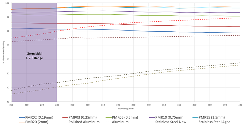
% Reflectivity versus wavelength of common materials
While the reflective performance of many materials decrease in the important UVC Germicidal range, Porex Virtek PTFE has consistently excellent results versus competitive technologies such as stainless steel and aluminum.
Typical Reflectivity of Porex Virtek PTFE Sheet vs. Aluminum and Stainless Steel
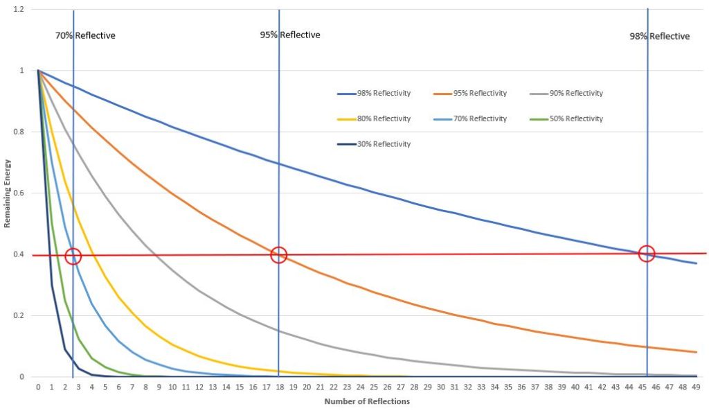
Number of reflections and estimated remaining energy for various levels of reflectivity
This chart illustrates how rapidly energy decays in a closed reaction chamber when reflectivity drops below 80%. The X-axis shows how many reflections you can expect until the initial energy drops to 40% (over 45 reflections for 98% reflectivity versus less than 3 for 70%).
# Reflections vs. % Energy Remaining

Total average irradiance in an ideal closed reflective lined chamber
This chart illustrates Sumpner’s Principle of Irradiance in a closed system. This principle estimates total irradiance that comes from the source plus irradiance that is reflected to get to an average steady state irradiance. The equation shows the exponential improvement that occurs over 90%, which can result in an average irradiance improvement of 10 times (from 70% to 97%!)
Total Irradiance in a Closed System
ETotal = ED + ER
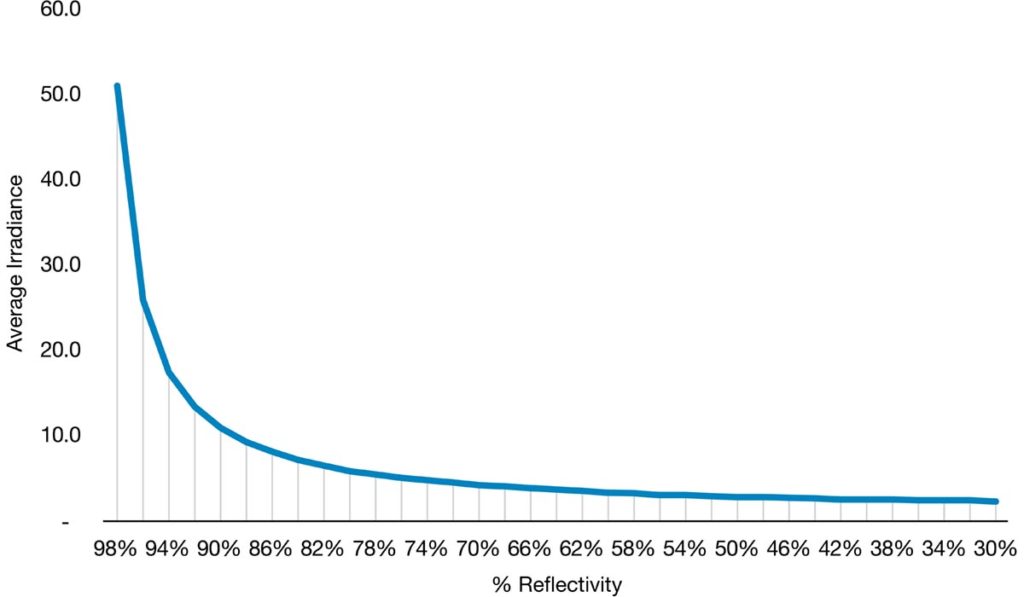
Data above based on Sumpner’s principle of irradiance in a closed system, ETotal = ED + ER, where ED is the source irradiance and ER is the reflective irradiance. ER is highly dependent on the reflectivity of the chamber and is calculated by ER = ED x (R/(1-R)) where R is the percent reflectivity as a fraction (ie. 50% = 0.5)